| 19th Century Technology/The Cigar Ships/Walter S. Winans
Reconstruction | |
|
The Walter S. Winans
Reconstruction |
|
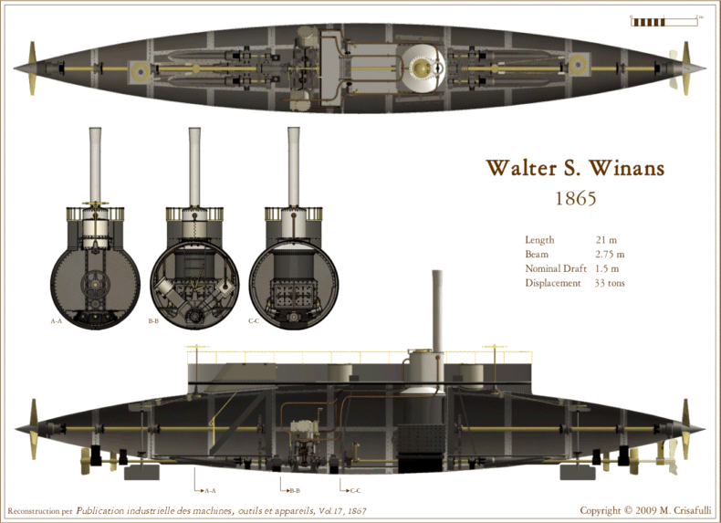
The figure below uses and is scaled to the dimensions published in the article. Some of the details, such as the top of the smokestack are speculative. A full compliment of nine propellers is shown, including the special submerged propeller aft (right in the figure) used for the cross-Channel voyage. This was probably the only propeller configured for that voyage and it is likely that no configuration included all the others at one time. | |
| |
|
There are some small discrepancies in the dimensions
both within the
Publication industrielle article and figures and with
other publications. The article's nominal 21 meter length and 2.75 meter beam
(~68.9 by 9.0 feet) is close to the dimensions mentioned elsewhere (72 x
9 feet). The figures show slightly different proportions with
the hull either narrower or longer by about 5%. Some of this
may be the result of the publication or reproduction
processes or may just reflect round-off in the quoted numbers. My scale drawings have
been adjusted to the nominal dimensions. My 3-D renderings have
additional discrepancies resulting from my reconstruction process, but
these aren't noticeable in the included images. | |
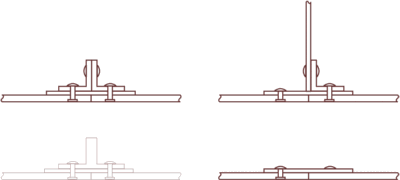
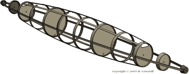
| Construction Construction details of the Walter S are apparent in the Publication industrielle figures. There were 50 hull plates attached to a frame as depicted in the cartoon graphic below. The plates were riveted to joining plates in three ways, as illustrated at right. The joints in the central compartment used circumferential angle irons as stiffeners (a less likely T-iron is also illustrated). The six bulkhead joints used a single angle iron in addition to the circumferential plate. The joints in the fore and aft cabins and the longitudinal joints used only joiner plates. As with the other cigar boats, the external rivet heads were likely flush with the hull surface. |
|
| |
| There
was no keel. Hull rigidity was achieved through the combination of
the hull plates, the joining plates, the bulkheads, and the stiffener
rings. The six bulkheads formed seven
compartments. The structure was symmetrical fore and
aft although internal mechanisms were not. | |
|
End Compartment | |
|
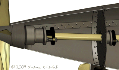
This small compartment at each end of the hull, a little more than five feet long and less
than four feet maximum diameter, contained the main propeller stuff box and
bearing, similar to the Ross Winans mechanism described in Patent
58744. The patent
describes two propellers, for vessels of large and moderate class.
Per the Publication
industrielle article114, 115
the propeller mechanism was designed so the propeller could be replaced with a stationary
conical plug that retained the hull spindle shape.
There was likely a small panel (not shown) in the bulkhead to provide access to
the mechanism, similar to the access hatches for the Ross Winans
described in The Engineer42. |
|
| Rudder Head Compartment | |
|
|
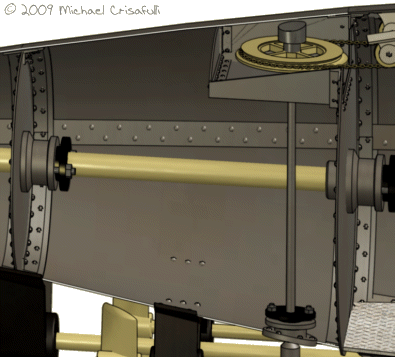
The second compartment, less than six feet long and six feet maximum diameter,
contained the rudder mechanism, again similar to but smaller than the Ross
Winans'. The
rudder shaft was offset about six inches athwart, unlike that of the
larger ship, which was curved to clear the centerline propeller shaft.
The upper part of the mechanism, the chain wheel, was enclosed in a box
attached to a cutout in the bulkhead. This
allowed the chain to run freely from the helm to the rudder and permitted access
to the chain wheel from the next compartment.
Here too there was probably a small panel or hatch in the bulkhead for
maintenance access to the compartment. |
|
Cabins
|
|
|
|
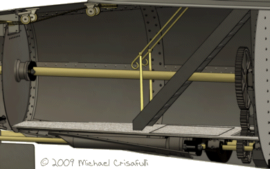
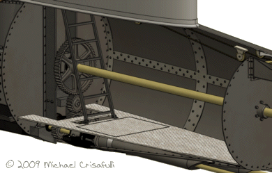
Rather than stairs, the aft cabin had a utilitarian ladder and was probably for the crew.
The
large bulkheads of the cabins, nearest amidships,
incorporated the thrust frame for the centerline propeller and supported the propeller
gear train. |
| Engine Room | |
| |
|
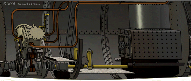
The largest compartment was the engine room, located amidships and nearly 18
feet long with a maximum diameter of nine feet.
The two engines occupied the forward section of the compartment and the
large boiler filled the aft section. The
engine crankshaft drove the power shaft via flexible couplers similar
to those described for the Ross Winans in The Engineer and in Patent 55835.
The ladder from the deck landed on the starting platform just aft of the
engines. There was a step past dual feed water pumps down to
the main deck stoker area in front of the
boiler. The
figures show the main steam piping and some of the engine control mechanism
but neither secondary piping nor gauges and control valves appear.
In addition to feed water lines attached to the pumps there may have been additional plumbing
and valves for clearing the bilge in each of the compartments using one or
both of these pumps. The
Engineer article42
mentions such a setup for
the Ross Winans. No coalbunkers are shown in the Publication
industrielle
figures. These were probably located on either side of the boiler and on the
curved
sides of the engine room. There
may have been some accommodation for coal storage in the cabins as well. The center section was enclosed by 18 hull plates. | |
|
Superstructure | |
|
Like the Ross Winans,
the Walter S superstructure and deck was set atop the spindle hull, leaving
space under the deck fore and aft. Although the shape of the
superstructure was symmetrical, its layout reflects the interior asymmetry. There was a large companionway for the passenger stairway forward that forced placement of the forward helm at the very end of the deck. A more utilitarian engine room hatch was located just forward of amidships. A similar hatch located just aft of the stack for access to the crew cabin left nearly three feet of space at the end of the deck for the aft helm. The boiler super heater extended through the hull and above the deck just forward of the stack. | |

The Publication
industrielle shows no anchors. The
Winans invention anchor and mechanism (Patent 31276) used on the Ross Winans and shown in
the gunboat drawings55, 56 were probably too
large for the Walter S,
especially with their attendant windlass.
The small boat probably used a conventional anchor stored on or beneath
the deck. The figures show
neither fittings for mooring nor gangway access.
Considering the fairly convenient
companionway and stairs of the passenger cabin, there was probably a gangway
gate in the three-foot-high railed bulwark. | |
|
|
|
(Source references are in the bibliography on the main cigar ships page.) |
|
Comments and questions are welcome. E-mail
me. |
This page and its content ©
Copyright 2009 Michael & Karen Crisafulli.
All rights reserved.
31 Jul 09
