|
|
orking primarily from the Naval Institute Press WJM/FPW
translation I have developed this design for Jules Verne’s Nautilus. Due to inconsistencies in the various contemporary and
later illustrations and the text, the text sourced descriptions were used.
A strict reading taking into account the technology of the period I
believe would |
|
produce a design very much like an enlarged CSS Pioneer. While staying faithful to the text, some license was taken for aesthetics – producing a more organic appearance than a strict reading would produce.
|
|
Exterior Points of Interest: ·
The spindle shaped hull has a volume 1543.4 cubic meters –
very close to Verne’s 1507.2 - with more surface area 1040.44 vice 1011.45
square meters (slight enlargement due to maintaining a smooth curvature and
providing sufficient space near the bow to accommodate Aronnax’s cabin and
other internal details) ·
As others have recognized a centerline mounted ram could not
inflict the damage on the ·
The topside “platform” is not a separate structure but a
flattened deck as used in many modern Albacore
style submarine hulls. ·
Alongside the hull are folding masts and booms and on deck
two retractable winches for deploying and recovering the trawling nets
referenced several times in the book. ·
At the forward and aft ends of the platform are retractable
winches and mooring rings (as Aronnax testifies they used to hold on to the
submarine when the party initially comes aboard). ·
The Pilot House and Beacon cupolas are of cylindrical shape
for best water-tight seal. The ports of the six-lens beacon are positioned
to provide all-around lighting without having a lens pointed directly toward
the Pilot House. Both cupolas are surrounded by a circular grab rail
attached near their peaks, slightly smaller in diameter than the base of the
cupola to permit retraction below the level of the deck. ·
In the middle of the platform deck is the recessed dinghy and
just aft the main hatchway. ·
Topside near the bow are two vents from which the discharge
of water/air/steam was witnessed. ·
The mid-ship mounted dive planes and screw have guards to
protect them from damage during ramming. ·
The oval salon windows are protected by sliding external
shields. ·
The diving chamber is accessed through the starboard side
mounted hatch/boarding ladder. ·
Below the hull is a single bow anchor, gratings for the
ballast tank inlets, and the dorsally mounted propeller type patent log. ·
On each side of the aft section of the hull are copper
radiators for cooling the propulsion equipment. |
|
Verne is very specific
about the dimensions of the Nautilus
and I have tried to keep this design as close as possible with minor
deviations to accommodate the internal layout. The dimensions specified
would result in a spindle shape also in accord with portions of the text. To
perform the calculations I used Michael Crisafulli’s suggestion and
divided the hull into 28 X 2.5 meter segments and calculated the volume and
surface area of each, totaling the results. Using an Excel spreadsheet I was
able to make various adjustments to get the desired hull curvature while
staying close to the original volume. I also needed to determine how the
hull was constructed as it would determine the hull thickness and interior
space. After settling on a hull thickness of 15cm (see section on hull
construction) I added blocks to the spreadsheet to calculate the interior
width of each deck while testing various deck elevations. In order to
accommodate the interior spaces described in the book I had to enlarge the
hull slightly to 1543.4 cubic meters from 1507.2. Internal limitations
included: ·
Width
of 2.3 meters at the forward bulkhead of Aronnax’s cabin to for a 2 meter
bunk athwartships ·
An
interior deck width of 4 meters at the forward engine room bulkhead for the
3 meter (10ft) wide Crew’s Mess/Cell with an additional 1 meter passage to
the Diving Compartment ·
Lower
deck height of 2.75 meters (9ft) sufficiently high that Ned Land could not
reach the ceiling of the Crew’s Mess/Cell ·
2
meter deck height on the upper deck ·
Minimum
1.9 meter height in forward cabins and passageway ·
Adequate
space above the upper deck for the retracted helmsman’s cage and beacon
and the socket for the dinghy without intruding into the upper deck overhead
·
Diving
Compartment space for a diving chamber and prep area large enough to
accommodate the required number of ready divers and diving gear storage for
the underwater excursions described During the design
process the external drawings were completed before the internal layout was
finalized. Certain internal features that affected the external appearance
(location and size of the Salon portal, boarding hatch, dive chamber and
pilot house and beacon cupolas) had to be established earlier. Note on calculations: The numbers stated in the text appear to have been calculated using the truncated value of 3.14 for pi instead of the extended value if using a calculating program or pocket calculator. With this value a hull comprised of a center 10 meter cylinder with a 30 meter conical section on each end results in values spot on Verne’s stated value of volume and near exact for surface area with possible rounding error. For this reason I also used the truncated value in my spreadsheet calculations; the resulting deviation being insignificant. As in the section on
hull design, Verne lays out very precise values for the surface area and
mass of the hull. A steel hull with the surface area and thickness given
would have exactly the mass described. The translation I worked from states
that this is the inner hull though the original text is vague enough that it
could be either. Due to the specific values stated in relation to the
overall dimensions I believe Verne is referring to the external hull. Stuart
Wier’s theory that Verne’s design was inspired by the Great
Eastern also backs this as the double-hull construction of that ship was
for structural rigidity, not as in modern submarines with a strong inner
pressure hull and a thin streamlining outer hull. The second hull details
are not provided but I believe it would likely have nearly the same
thickness for this same reason. Riveted construction of
the time required access to both sides of the assembly. The hull would
either have to have both layers spaced close enough to rivet through both
hull layers and T-rail at the same time or be spaced far enough apart for a
workman to crawl into the void space to back the rivet. The latter would
require a hull thickness such that it would not be possible to fit the
interior as detailed.
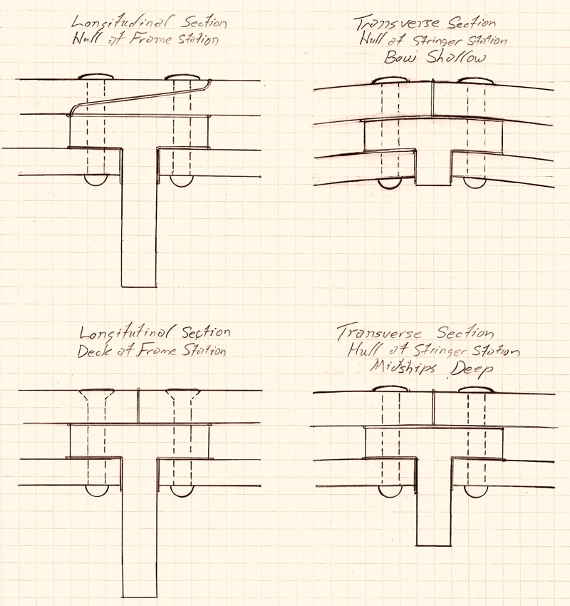
In the attached sketches
I have an outer hull 5cm thick separated by a 5cm thick T-rail frames and
stringers from an inner 3.75cm thick inner hull. The assembly is through-riveted with the outer rivet tails hammered nearly flush as on the CSS Hunley
for reduced drag. Rivets on the topside deck are also countersunk for a
smooth walking surface as described by Aronnax on his initial boarding. The
final hull thickness including the height of the internal rivet heads comes
to 15cm. Plates on the topside
deck and plates on each ring segment are butt joined with the T-rail
providing the joining surface. Each hull ring segment is overlapped with the
segment aft. To seal the plates I propose a method I found referenced for
sealing boilers – lead foil gasket material sandwiched between the plate
and T-rail surfaces drawn tight by the cooling rivets. Ram At the time of the
collision with the
Scotia
Nemo states that the Nautilus was
cruising at a depth of 2 meters but there is no reference given. Submarine
depths are usually given as depth to keel but this would result in a depth
of at least 7.2 meters when running surfaced (greater if the design
incorporates an external keel). Instead I interpret the 2 meter depth as 2
meters below normal surfaced trim. This places the tip of a centerline ram
at a depth of approximately 5.2 meters, well below 2.5 meters where the The ram itself is a
single large hollow steel casting incorporating the air reservoir and capped
with a domed bulkhead becoming an integral part of the hull. The riveted
ram/hull joint is reinforced with a steel band, a steel shield across the
top of the hull providing additional protection in a collision, and joined
to the forward extension of the keel. Ship’s Boat The ship’s longboat is
stored in a recessed socket in the center of the platform as described in
the book. In my initial designs I used standard davits as the means of
deploying and recovering the boat but found the rotating arm equipment
described on the Vernian Era page much more practical and efficient. However
instead of the boat being rigidly attached and flipping in the process I
have a set of pivoting bolts at the bow and stern which allows the boat to
remain upright during the process similar to a Ferris wheel car. Withdrawing
the bolts from the frame allows quick deployment even when still in the
storage socket. The starboard view of the Nautilus
in its “dirty” configuration shows the longboat at the maximum vertical
point in its arc – approximately midpoint of the deployment/recovery
process. Visible on the lower hull is the access hatch. Capable of being
maneuvered by minimal crew the boat favors a lightly constructed hull. Nemo
even describes it as such during Aronnax’s tour. This would require that
the hull be flooded when operating at depth as suggested by Greg Sharpe. Unfortunately a lightly
built boat creates plot problems. In the chapter “ Mooring Equipment The mooring gear I have
provided includes 5 pairs of retractable deck cleats, a folding bullnose
mooring ring and retractable electric winch at the bow and stern, and a
single bow anchor. The hull is also configured with an external keel and fin
allowing the hull to rest level on the sea floor. Although Nemo’s
aversion to land would make much of the gear seem superfluous, it is still
used during the stop at Nemo’s volcano base in the chapter “The
Submarine Coal Fields”. Also in the chapter “The Torres Straight” Ned
makes specific mention of using the anchor to kedge the Nautilus
off the reef and that Aronnax confirms that Nemo will not use this technique
and simply wait for the tide to refloat the boat but the implication is that
the Nautilus is so equipped. |
Interior: |
|
(Click graphic for full size image) |
|
Crew Complement and Accommodations Verne provides little
evidence of the crew complement other than periodic references to working
party and excursion sizes. This becomes an important plot element as Ned
evaluates escape options but leaves important gaps in determining crew
size and accommodations. The largest party specified consists of twenty
sailors but actual crew size would as a minimum include additional crew
still remaining at vital watch stations. There is mention of the 5 meter
crew’s quarters as well as reference to two smaller cabins: a two-man
cabin that is assigned to Ned and Conseil, and the cabin near the crew’s
quarters where Aronnax examines the injured crewman. From the interior
layout I was able to fit in additional cabins for junior and petty
officers, and one for the first officer just aft of the chart room. The 5 meter cabin was
able to fit 2 x 3-bunk stacks on the inboard wall and 2 x 2-bunk stacks
along the hull (there being insufficient overhead space due to the
curvature of the hull for an additional bunk) for a total of 10 bunks with
several lockers for personal effects. If utilizing “hot bunking” with
two watch sections there is room for 20 seamen. The four additional
two-man cabins would provide quarters for two junior officers standing
two-section officer of the deck and six petty officers: e.g.
Quartermaster, Chef, Boatswain, Engineman, Electrician, and Coxswain. In
the Dining Room I provided four chairs allowing Nemo to dine with all his
officers as was customary of the time. With the captain and
first officer this totals 30 crewmen when the Nautilus first went to sea. At the time the protagonists came aboard
there had been at least two crewmen lost to leave a vacant cabin for Ned
and Conseil. This is confirmed when attending the funeral in the coral
cemetery as there had been other crewmen previously interred at his
location. Aronnax's Cabin Because of the limited space the furnishings are
built-in instead of free standing. Due to the extreme taper, the flat
floor is only 1.8 meters wide at the aft cabin bulkhead leaving only
enough room for the two required doors. This left the only space for the
bed as mounted athwartships on the forward bulkhead. The length of the bed
set the minimum hull width as 2.3 meters at this point with 2 meters for
the bunk and an additional 0.15 meters for the thickness of the hull at
each side. Despite these restrictions there is still adequate space for a
Twin XL size bunk, a full-height wardrobe built into the larboard side and
a washstand and mid-height locker build into the starboard side. As the
bunk is mounted at mid height of the forward bulkhead there is sufficient
space below to stow a small dressing stool. Nemo's Office (Cabin) Although I had not previously considered it, I
agree with Michael Crisafulli’s theory that Aronnax’s cabin was originally the Captain's sleeping quarters
and this space was originally Nemo's office/workspace. This set the
direction of the furnishing of this room. There is a desk and chair at the
aft bulkhead, and along the starboard wall forward is Nemo's instrument
board and aft built into the wall is a small settee described as a bench
during Aronnax’s tour. These are the original furnishings. When Nemo
vacated his sleeping quarters to Aronnax he moved a small iron bed
(basically a cot) and a small washstand into this space. The additional
items make for a crowded room. Grand Salon In order to accommodate the hull slope due to the
raising of the hull line to the bow, the floor is terraced. One advantage
of this is that the height of the ceiling and the forward end is still
nearly 5 meters above the floor level where entering at the aft end making
for a more open impression. Although the ceiling is partly covered to
conceal ventilation ducting and the protuberances caused by the deck
features, the walls are left bare to follow the curvature of the hull
though paneled and wall papered. From the side view the amount of
available wall space for hanging paintings, arms and tapestry is apparent
though approximately the upper third would be unusable for this purpose
due to the inward hull curvature. Initially I intended there to be sliding
panels to cover the observation ports but this proved unsatisfactory as
they either would absorb wall space if mounted internal to the salon or
required a thicker hull section if they were to retract into the walls. I
finally decided the panels would be mounted external to the hull which
would also provide protection to the glass ports during collision. At each corner of the room are panels cutting off
the corners of the space. Set into each of these corner panels are
recesses which contain the marble and bronze statues. On the upper terrace
at the forward bulkhead is the pipe organ and stool. Behind is the
"costly mosaic table". Next to that facing aft is one of the
display cases built into the terrace. On the mid terrace are two divans.
Though not indicated they are mounted on central pivots and swing arms
allowing them to be swung out or rotated to face out the ports located
immediately behind them. At the aft end of the mid terrace is a 2 meter
pedestal upon which sits the clamshell fountain. The pedestal also
conceals the pressure chamber containing the anchor winch and chain locker
which is open to sea pressure through the chain chute and keel of the
boat. On the lower terrace built into the aft side of the pedestal and on
each wall are additional display cases. On the aft bulkhead is the ladder
to the upper deck. Placing the ladder at this point permits Aronnax and
Nemo to transit from the forward part of the boat to the upper deck
passageway during their tour. It also allows Nemo rapid access to the conn
from the forward areas if required. Pilot House and Chart Room The Pilot House consists of a 2 meter square lower
room with a movable cylindrical cell above. The cell consists of a tapered
cylindrical cupola with an open basket suspended blow for the occupants to
stand. The cupola slides in a guide sleeve with a seal between. Retraction
and extension of the cell requires only a simple mechanical jack as the
operation is performed on the surface when there is no external pressure.
When in position the cell is secured from movement by a lip around the
lower edge of the guide sleeve when retracted or by blocks when in the
extended position. The cell is accessed by a collapsible straight ladder
and hatch in the basket floor when either raised or retracted. The cell
contains the ship's wheel forward, the engine order telegraph to larboard
and the diving planes control wheel to starboard. Both wheels operate
telescoping shafts through bevel gears through the floor of the basket to
operate the control surfaces. Aft of the pilot house on either side are panels
to control the trim, drain, and ballast systems on the larboard side and
to control the ventilation and air supply systems to starboard. In the center of the chart room retracted into the
overhead is the periscope (see my arguments for the existence of a
periscope). Further aft is a large chart table and locker. Electrical Compartment The power cells
described in the chapter “Everything by Electricity” are more akin to
fuel cells as the chemical components are replaced as they are consumed in
order to continue generating power. Compared to a primary battery where
once the reactants are expended it is disposed of, or a secondary battery
where the chemical process is reversed by recharging, the power can be
generated indefinitely as long as sufficient replacement reactants are
available and the waste products are removed from the cells. For this
purpose additional equipment is installed. To starboard is the cell
conditioning equipment to extract the amalgam from the cells, remove the
expended reactants, replenish the sodium, and return the reconstituted
amalgam to the cells. On the larboard side is
an instrument board to monitor individual cell voltages, temperatures, and
reactant levels. Also to larboard is a switchboard for isolating and
bypassing individual cells and controlling distribution of electricity to
the rest of the boat. Aft are the power cells
with a catwalk running between the two banks and aft to the Motor Room
bulkhead. In the deck is a hatch and below a ladder to access the bilge
area and the bottom drain cocks on the power cells. Motor Compartment For the main propulsion
motor I initially considered a rotating armature type. While this type in
its primitive form had been invented in the 1830s and I believe Verne
would have recognized its greater potential, I decided a reciprocating
design would better fit the description in the book. In order to pack the
most motor into the cramped space at the aft end of the engine room I used
a radial design similar to air-cooled radial aircraft engines. The
reciprocating motor uses electromagnets in four rows of fixed water-cooled
stator rings with iron core slugs in place of the pistons driving
connecting rods and a common crankshaft. Located at the aft end is the
distributor which controls the timing of the magnets. The distributor
timing is shifted to reverse rotation. At the forward end is an
open 4-speed reduction gearbox to permit the motor to operate at its most
efficient rpm regardless of the shaft speed. Ships bells are answered by
shifting to the appropriate gear for the bell ordered. Levers on each side
operate the gear train and clutch; the gear train transferring power to
the main shaft which passes below the motor and out through the shaft
seals. The motor, gearbox, its operating levers and associated linkages
roughly conform to the description in the related passage in the book. At the forward bulkhead
is a board to monitor motor operating conditions and on either side are
two cooling water pumps to circulate cooling water heated by the motor and
power cells to the radiators mounted externally on the hull. Crew’s Mess (Cell) It is unlikely that a
room of this size would be set aside just for a brig. The only other
reasonable use as others have noted would be as the crew’s common area
for dining and recreation. To comply with the text the room’s placement
required having a door near the base of the central stairway and a door 10
meters from the door to the Dining Room. This places the aft wall of the
room at the forward engine room bulkhead. It also required a 2.75 meter
ceiling high enough to be out of the reach of Ned Land. Diving Compartment This compartment
contains the Diving Chamber with internal hatch and external combined
hatch and boarding ladder. To larboard is the Diving Locker for storage of
the diving suits, helmets and breathing apparatuses. To starboard is a
small arms locker for ready storage of the pneumatic guns. I wanted this
area to be large enough to fit four to six divers in the prep area and
another four in the chamber. The locker would also need to store
sufficient number of diving suits to equip the sixteen men that
participated in the funeral precession. The Periscope Arguments for a
periscope on the Nautilus: ·
The
simple periscope is credited as being invented in 1647 and the submarine
periscope in 1854. ·
Optical
technology of the time was advanced enough to overcome much of the image
brightness and quality issues that had been experienced. Advanced
multi-element optical eyepieces and objective lenses had been developed
associated with astronomical telescopes by this time. It would have been
an issue more of application than capability. ·
Aronnax
is in the pilot house/chart room only for the transit through the Arabian
Tunnel and therefore never observes how the Nautilus
is navigated with the cupola retracted. ·
In
a biography of Verne in regards to “From the Earth to the Moon” the
author stated that Verne avoided using technology that to the public
appeared immature (rockets) in favor of technology more well-known
(cannon) to create a more believable story even if the former provided a
superior solution. In this case I believe Verne would have included the
periscope if it had been more well-known. Instead he just avoided the
subject by not allowing Aronnax access to the pilot house during the
attack; the only action requiring its use. ·
Although
a practical rotating submarine periscope had not been developed, a fixed
(non-rotating) periscope could be fabricated; using multiple tubes to view
various directions. Though not entirely
impossible, a long fixed periscope that extended above the surface would
still pose many issues including extending down through the library when
retracted, misalignment of the mirrors due to tube flexing, longer time to
retract into the hull prior to impact, and greater light loss, and
excessive drag associated with a multiple tube design compared to one that
extended just above the hull. A short periscope could be quickly retracted
shortly before impact to prevent damage. The periscope I have
decided to use is a fixed multiple-aperture periscope similar to that used
on armored vehicles covering the 180 degree forward arc. This would
provide visibility not significantly inferior to the extended pilot house
with the exception of vertical field of view and to the aft. The upper
assembly is extended to protrude approximately 25cm above the deck and the
lower assembly with the viewing ports is retracted into the overhead of
the chart room when not in use. It would therefore not have been visible
to Aronnax during his brief time in the room. Bulkheads and Watertight Compartments In the text the Nautilus
is divided into four, possibly five water tight compartments. Verne
specifically identifies the bulkhead between the forward cabin area and
the salon, between the library and the dining room, and at the forward end
of the engine room. He also alludes to another when he states the ladder
to the dinghy is between two watertight bulkheads. As it is mentioned
prior to entering the crew compartment it is not a reference to the engine
room bulkhead. This would place another bulkhead between the dining room
compartment and crew compartment. Note that these doors and bulkheads are
not referred to as being watertight when Aronnax initially walks through
the forward areas; it is only on his return trip through the boat that
this is stated. He also states the engine room is divided “by
function” into two areas but it would also be reasonable that it also be
divided by another bulkhead. This would minimize the volume that could be
flooded without isolation. This would also apply to the door between the
library and the salon – which is also a very large volume. Because of the low
reserve buoyancy (150 tons – 10%) it would be logical to have greater
subdivision in the event of flooding. I have therefore separated the Nautilus
into seven watertight compartments adding the two bulkheads mentioned. I
have also interpreted the “double door” between the dining room and
library as two doors face to face, opening opposite each other from
opposite sides of the bulkhead. This configuration would ensure that
regardless of which compartment on either side of the bulkhead flooded,
the water pressure would positively seal the hatch on that side without
having to rely on the dogs. This is not required on modern submarine doors
but would be beneficial considering the materials technology of the time
and the extreme diving depths the Nautilus
is capable of. I also used the double-door configuration at the engine
room bulkhead. This placement as well as the direction of the doors was
based on evaluating each compartment’s vulnerability to flooding and how
critical the compartment was to recovering from the casualty or saving the
crew. Other Miscellaneous Details ·
The
Dining Room, Library and Galley follow the book descriptions with
additional details previously given. ·
At
the foot of the first flight of the central stairway is the tackle locker
containing the nets, blocks, and line for the trawling gear. ·
On
either side of the forward upper deck are lockers for storing the sodium
reserves in oil-filled canisters. ·
Ladder
access to the longboat is on the starboard passageway between the first
officer’s cabin and the tackle locker. ·
In
addition to the arms locker in the Diving Compartment there is a larger
armory in the upper gallery located near the gangway to facilitate
repelling boarders. ·
The
Blower Room located under the central stairway contains the ventilation
air blowers and air compressors. ·
Midships
under the lower deck, accessed from the Blower Room is the Pump Room
containing the Trim, Drain, and Ballast Pumps. ·
A
dumb waiter is located near the central stairway easily accessible from
the Galley on the upper deck and the Crew’s Mess and Dining Room below. ·
The
Aux Trim Tanks, Forward Trim Tank, and Aft Trim Tank constitute the
additional 100 tons of ballast tankage described by Nemo. ·
A
potable water storage tank is located beneath the floor of the Salon.
|


|
|