|
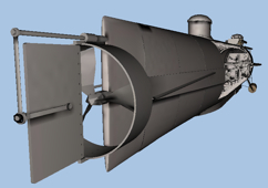
Click the graphic at right for a 3D low-resolution cutaway reconstruction (opens in new window, model takes some seconds to load - browser must support WebGL). |
|
The Hunley Reconstruction
|
Click the graphic at right for a 3D low-resolution cutaway reconstruction (opens in new window, model takes some seconds to load - browser must support WebGL). |
|
 |
A set of ballast weights are attached to the hull by bolts, some of which could be released from inside the cabin.
The captain's station included controls for the rudder and dive planes, a compass, and depth gauge.
The bow and stern are iron castings.
The crew section has stations for eight crewmen although only the seven cranking stations were manned for the last mission.
The Hunley's portholes are in noticeably different positions on the two hatch towers. These differences are very likely by design.
The hull begins to taper at the hatch sections.
Click for some thoughts on the hull shape.
Historical accounts report the center section of the hull was made from a boiler.
The dive planes are positioned forward of the center of floatation.
The propeller was driven by a crank chained geared to a flywheel on the propeller shaft.
The rudder mechanism looks odd. How did the Hunley steer?
A bellows air pump was found beneath the snorkel box.
The upper and lower parts of the hull are joined by strakes along the sides.
The ballast tanks are separated from the cabin by bulkheads, open at the top.
The tapered tank sections are constructed from quarter panels.
The internal steering linkage differs from historical depictions.
The Hunley's torpedo was partly carried on a spar bolted to the bottom of the forward casting.
The deadlights on the top of the hull were more complex than thought.
|
|
In early 2017 the Naval History
Command published an extensive report detailing the Hunley recovery
operations and much of the archaeology conducted on the sea floor. This
material is augmented with photos and drawings that are much more recent.
The latest revision of my Hunley plan takes advantage of this report as
well as photos after the hull exterior was cleaned of concretion. I have
added the likely torpedo configuration and speculative placement of two brackets
found near the Hunley that likely fastened the upper spar boom to the hull as
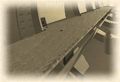
shown by Chapman. I started my original plan way back with dimension and detail information from the National Park Service Site Assessment Report, available via a link on my Hunley page. Reports and photos of removal of the hull plates provided significant data on the size of the plates. The central hull took form from rivet counts and examination of a number of photographs, and from reported dimensions. I’m confident of the accuracy of the four removed plates, but the two remaining plates are more speculative. Finally, I adjusted the hull shape based on close examination of laser scan images published in the Friends of the Hunley Blue Light newsletter. A more recent change, dividing the formally long most forward and aft tank quarter plates in two, is much less accurate, based on a two or three cropped Post and Courier photos. The photos show a narrow plate on the top of the hull joining the forward ballast tank quarter panels together. I've assumed this plate runs the length of the tank section and that a similar plate is used on the bottom. Likewise I've added these structural details to the aft section. This narrow plate is consistent with Chapman's painting, where it appears as dark line along the top of the aft hull. Chapman also depicts the division of the aft tank quarter-panels mentioned above. Click the now obsolete low-resolution drawing below for a detailed five-view plan of the Hunley. (Note that Internet Explorer reduces the image size to fit its window. Click the expansion icon in the lower right-hand corner to view it full size.) |
||
 |
||
The hull taper begins with the hatch panels. The tapered sections consist of 16 quarter panels and the bow and stern castings. The ballast tank sections are forward and aft of the hatch panels (the tank bulkheads are actually located several inches into the sections defined by the plate seams).
Both the bow and stern are iron castings. Chapman’s painting shows
the stern casting clearly. The historical reports and the
Chapman material have been found to be sources of accurate information. I
used them extensively. |
|
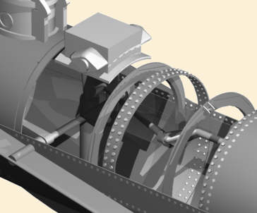
The slightly out-dated view above shows my sixth version of the
crank. I've mounted it one inch below and ten inches to starboard
of the centerline, supported by new brackets. Late interior photos
clearly show crank mounts bolted to the strake by an upper plate
bolt. The lower part of the mount is hidden in the photos but is
most likely bolted at the bottom of the strake. There is a small
possibility it is attached to the adjoining frame ring as I thought
originally, but I have no photographic evidence of this. Notice that much of the crank mechanism would be below the halfway mark of the excavation, consistent with the delay in
uncovering it (remember, the hull lists about 45 to starboard). Visual evidence places the frames in the sections exposed for excavation about 25 inches apart. I placed the others using interpolation and extrapolation from 22 to 25 inches apart. The crank radius pictured is eight inches. The published photos show varying angles from crank position to position, perhaps more consistent with Alexander's description ("cranks at different angles") and archaeological findings ("evidently bent at odd angles"). To me this suggests that the crank is constructed of sections bolted together. There may have been some loosening and relative shifting of the sections during operation that was not corrected when the joints were tightened. There is a clear benefit of offset cranks: each crewman would rock back and forward out of phase with the next, preventing the action to induce a rolling motion to the boat. |
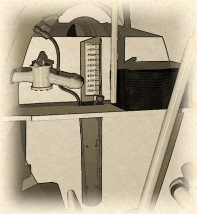
| The slightly more recent rendering at right shows details gleaned from the 2002 Smithsonian Seminar presentation and from photos from National Geographic magazine and the updated Friends site. The forward sea-cock is located on the port side of the shelf just below the inlet for the depth gauge. In 2005 the actual gauge was revealed to be three feet high, so this reconstruction is much too small and probably incorrectly positioned (see Depth Gauge below). | 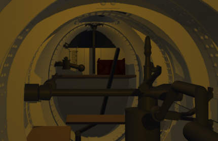 |
| It's still not clear exactly how the tiller connects to the rudder
linkage. The photos appear to show a bend at the bottom of the tiller connecting to another feature a
few inches farther to port. A long sturdy cylinder seen
running the length of the cabin
on the floor almost under the bench is actually a pipe between the two
ballast tanks but a narrower rod further under the bench is
probably the steering linkage. It is possible the sharp angle at the bottom of tiller is a
separate feature not associated with the steering mechanism but I
think it is connected to the second rod. The depiction above incorrectly shows the tiller
attached to the inter-tank plumbing. The hatch latching mechanism is in its approximate position and I've made an attempt to show the hinge I believe attaches it to the cabin overhead. Lastly, the rendering shows a bench for Dixon, floating in space for now until I can work out mounting details. |
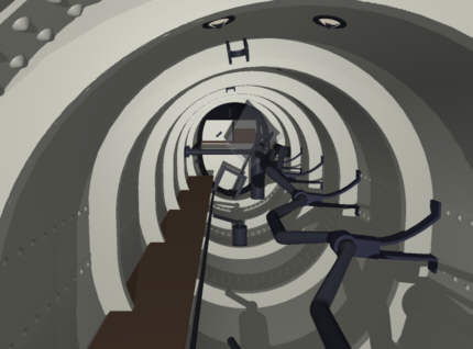
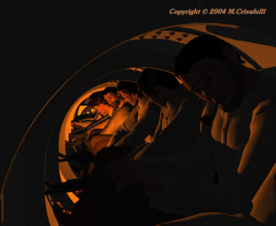
I've place the crewmen in the rendering at right. The camera is about at the location of the bellows. It's definitely a tight fit. The rendering below, looking forward, shows one crewman cranking at his station. |
 |
|
|
I initially positioned a small depth gauge as shown in the older rendering
above, but the actual gauge, composed of metal and glass tubing, was
nearly three feet tall. Contrary to press
reports, comparison of an x-ray published in The Blue Light with
older interior photos verifies it was mounted on the forward bulkhead approximately as pictured
at left.
The shelf mounted on the tank bulkhead appears to have a notch on its
bulkhead edge to accommodate the gauge apparatus. |
| 
|
| I've used a small card as a depth scale for the reconstructed gauge, but it occurred to me that the metal plate suggested recently as part of a possible battery might be part of the gauge. Its 4-inch width is similar to the gauge mounting board and it could fit behind the glass tube. Although it is thicker than needed, its 16-inch height could have provided a depth scale of 15 or 16 feet. However, this is inconsistent with the the longer glass tubing length reported in 2016. |
|
The Crank
The web cam views and published photos show that the handles do not
extend at right angles from the axis, but are angled in. The
earlier reconstruction above left, with the single crewman, is simpler than the actual crank appears in the
photos. It uses a uniform diameter where the photos imply a
narrowing from the handle to the journal, as shown above in the other
views. The cross sections may
not be circular and, as mentioned above, it is possible the crank is constructed from
discrete parts rather than a single shaft. Apparent
offsets at the handles visible in one early photo appear on closer examination
to have been an illusion caused by unremoved fill. The concretion and preservative
wrappings made this kind of remote interpretation chancy. What are characteristics of the crank? |
|
 |
Alexander’s drawing shows eight
cranking stations between the two hatch areas. In fact there are
only seven crank positions. There is room on the bench for an
additional crewman, but he would only have had the bellows and pump to
operate. The diving plane
axis crosses the hull just aft of the forward hatch in the snorkel box
section at the forward end of the crew bench. Removal of the air box plate confirmed the location of a frame ring in the expected location. Another forward of the diving plane appears in some later photographs and there are more in the ballast tanks. See the discussion below for more on the rings. |
|
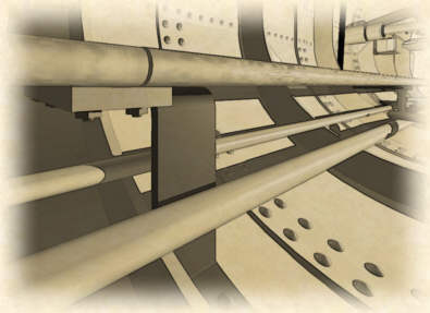
The bench has three separate sections totaling nearly 18 feet in length.
An early report
mentioned bench brackets "bolted to the hull exterior" and
fastened to the bench "with square-headed and countersunk
fasteners". The brackets are not apparent in any photos
released to date. My first guess was that they would be similar to those
for the crank and depicted two possibilities in the drawings at
right. The upper version would not have been uncovered until
excavation was nearly complete. The part fastened to the hull would
be embedded in concretion and the bench part only visible from
underneath. The second possibility, which seems
sturdier, would have been visible sooner, but still might have been hidden
by the canteens and other artifacts and features under the bench. |
|
|
|
|
| Photos
published in the the Friends' Blue Light newsletter led me to
consider bench
mounts attached to the stiffener rings, but the defining information was
the Hunley segment on Turner South's Southern Living
broadcast in 2005. The lower part of the brackets is not visible in
the video and speculative in the graphic. At least one may have the
upper fastener bent down rather than up as illustrated. Such a
bracket with a different lower part could be easily described as C-shaped. |
|
An informal exchange with
reporter Brian Hicks, author of the Post and Courier article, and close
examination of the Southern Living video led
me to my current reconstruction using the third possibility above, illustrated at
right and below. Parts of several brackets are clearly visible in the
video, shot during the removal of the aft bench section. All are bolted
directly to the hull plates, next to stiffener rings. Brian informed me that just two fasteners were used to attach each of four brackets to the bench itself and that they are about four inches wide. |
|
|
Examination of the video supports Brian's recollection
of four brackets. There appear to be two for the first section and one
each for the others. The joining block, visible in the graphic just
above, provides required additional support for the second section. The
third must have had another support, probably near its aft end in the jumble
of plumbing and concretion visible in available images. Move the mouse pointer over the graphic at left to see several brackets under the bench. Many thanks to Kim Johnson for providing Southern Living video, not available in the North, for my analysis. |
|
That the bench is made up of three sections of
approximately equal length is interesting. Maria Jacobsen stated
that the pieces don't fit well, indicating possible modifications. An
18-foot bench could have been installed while the hull was under
construction, but after that replacement could be managed only with
shorter pieces. Six-foot sections could not be brought into the
cabin through the narrow hatches with their nearly foot-tall towers, but
they could be jockeyed in through the snorkel opening if the box and
bellows were removed. Chapman's starboard-side drawing indicates the
box was removed to access the cabin after the second sinking, indicating
this was not necessarily a very difficult operation. |
|
The Stiffener Rings The frame rings were the
first interior features revealed and presented the first puzzle to me.
As
the cabin fill was removed, the web cam began to reveal the ring
structure. Although there was considerable concretion, I interpreted
a center ring sandwiched between two slightly thinner ring plates with a
smaller outer diameter. A more massive feature was visible on several
rings close to the top of the cabin. |
|
Return to line
drawing above. |
|
The Hunley has at least one design characteristic that would have helped keep the boat on an even keel. Offsetting the individual crank handle positions by an angle prevented the crew from synchronous back and forth motion. There are other less obvious details. The crew, with the exception of the captain, sat on the port side. Although the confines of the cabin would force them to lean toward the center, contrary to a press release most of their mass would still be on the port side. |
|
|
This
was partly offset by the weight of the crank, which is on the starboard
side. More than 60 cast
iron ingots of various shapes and sizes visible on the cabin floor likely compensated the rest. |
|
|
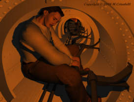
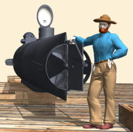
How big is the Hunley? These renderings show
the current reconstruction with a figure to scale, based on the Chapman painting. The soldier is 5 foot 8
or 9. | 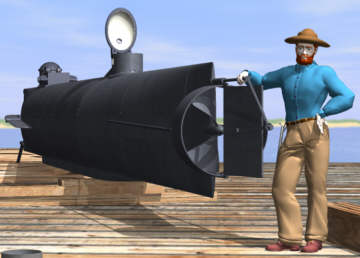
|
|
Here are some crewmen seated in the crew cabin.
I've placed a horizontal ten-inch wooden bench and crank based on interpretation of
early published interior
photos.
|
Poser figures rendered in RayDream Studio |
|
What's coming? |
I'm slowly refining and improving the 3D model as I speculate about interior mechanical details. Almost no new information has appeared and I'm not optimistic for the near future. I am replacing the generic Poser figures with my reconstructed crew and working on a detailed Chapman reproduction. |
Check back now and again for updates |
|
Experience my Hunley archaeological interpretation. |
|
| My
Reconstruction Tools
I've occasionally gotten queries about the
tools I use to create this reconstruction, so I've added this little
section. They've served me very well on this and other projects and their
utility goes far beyond this application. I also use several paint
programs including Micrografx Picture Publisher, Corel PhotoPaint,
and Adobe Photoshop, each of which has a particular strength. | |
| My plans were created in CorelDraw, which I also use for 2D analysis and to create templates for individual 3D objects. Bundled as a graphics suite that includes PhotoPaint, you can buy the latest version this versatile and useful tool at amazon.com by clicking the link. (Earlier versions are also available.) |
|
| The 3D models featured on these pages were created in RayDream Studio, a non-defunct program. For later images, I transferred the modeling to Carrara, the RayDream follow-on that combines most of the capabilities of the older program with many new features. |
|
| The human figures were developed and posed in Poser, a unique entry-level program that has improved considerably over the years. It works by itself or with Carrara directly or through a plug-in, depending on the version. You can purchase the latest version of Poser at amazon.com, by clicking the link. (Earlier versions are also available.) |
|
|
|
|
|
|
This page and its contents
© Copyright 2001, 2002, 2003, 2004, 2005, 2006, 2008, 2016, 2017 Michael & Karen Crisafulli.
All rights reserved.
28 Sep 17