| he keel ballast, along with numerous small weights found on the cabin floor and in the ballast tanks, stabilizes the submarine, which would be top heavy with its heavy cast-iron hatch towers. |
| It would be useful in an emergency to quickly release the ballast to increase the sub's buoyancy. Once again I return to Alexander's 1902 account for information. His drawing shows three release mechanisms on the cabin floor. | |
|
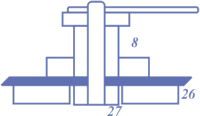
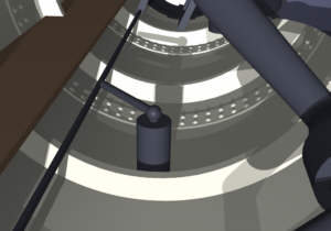
The detail at right reproduces his release mechanism, which was captioned "8, keel-ballast stuffing box", "26, cast-iron keel ballast", and "27, bolts". The rendering below shows a very similar mechanism as revealed in a published photo. |
|
|
|
Early press reports and published photos indicate three mechanisms. There appear to be seven separate cast-iron segments. The two oddly shaped end segments are most likely permanently fastened. The others are smaller, regularly shaped, and could be held by a single sturdy bolt. |
|
With only three releases
two of the five could be permanently attached or could be held in place by the
other three and automatically released with them. There is also a
small possibility of additional releases in the forward and aft sections
among the jumble of pipes and valves associated with the ballast tank
pumps. However, releasing all the keel ballast would run the risk of
inverting the submarine because of its top-heavy configuration. |
| One Possible Mechanization | |
|
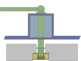
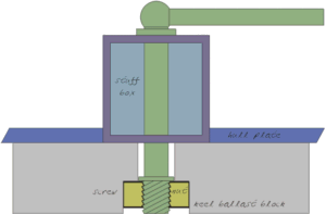
The diagram at right shows one way a release mechanism could work. The holding pin is threaded into a nut that is countersunk into the ballast block, similar to Alexander's graphic. The pin, which has a lever on its upper end, turns freely in its stuffing box. |
|
|
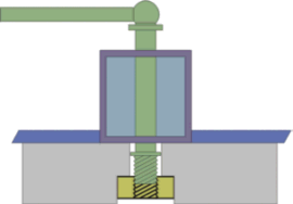
The diagrams below show the release in operation. On the left, the lever is turned to unscrew the weight, which drops and eventually falls free when the screw releases the nut. |
|
|
|
|
In the situation shown on the right, the keel weight is trapped, such as might be true if the sub were sitting on the bottom. In this case, the pin rises in the stuffing box as the nut unscrews. The weight is released when the pin is free of the nut, this time by vertical movement of the pin. |
| Another Possibility | |
| As I've thought about it I've come to favor an alternate mechanization. Examination of the three release handles as shown in various photos reveals they are all set at approximately the same angle, about 45° port of the centerline. Although the screw mechanism described above is not ruled out by this configuration, it does suggest a different design. | |
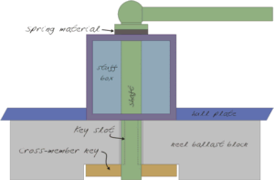
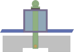
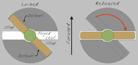
| Rather than a screw, the release mechanism might employ a simple keyed lock. The shaft would be pierced at its lower end by a cross-member key. Likewise, the keel ballast would be cast with a key slot of slightly larger size. Normally, the key is rotated away from the slot so that the ballast is locked in place. |
|
|
When
the key is rotated so that it matches the slot, the ballast is freed and
falls away. To provide an
indication of the key position in the cabin, the handle is set at the same
angle to the shaft as the key. |
|
|
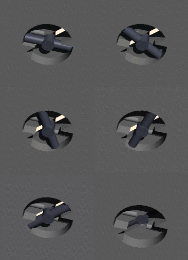
A slight ridge detent would require significant force to begin the turn to engage the slot. The shaft could be spring-loaded – a rubber or leather bushing would work as well as a metal spring – so that it could be rotated over the detent. Such a mechanism would be sufficiently secure to prevent accidental release, but operate quickly when release was necessary. |
|
|
| The actual angle of all the handles implies that the slot in the ballast is oriented athwartships or side-to-side. With the ballast locked the handle is conveniently out of the way under the bench, but within easy reach. When operated for release it points directly out from under the bench. | |
|
This mechanism has advantages over the screw described above.
While the screw can be easily fouled and jammed by salt or rust, this
simpler mechanism is less susceptible.
The screw, which requires multiple turns to complete release, gives
little or no indication that the ballast is locked, released or anywhere in
between.
If this alternate evaluation is accurate it appears that the crew made no attempt to release the ballast. |
|
|
What do you think? |
|
Page and contents
© Copyright 2001, 2005 Michael & Karen Crisafulli.
All rights reserved.
4 Jul 04
