5-View Depiction of Walter S based on Nillus figures

At my first look several years ago, there appeared to be a dearth of information about the cigar boat that probably had more water time than any of the others, but examining all the then available descriptions gave a better picture.  Most sources give only the dimensions, 72 feet long by 9 feet beam, perhaps the displacement, about 33 tons, and perhaps also the use of four propellers, two at each end.  Dodds5 mentions two masts and a bowsprit.  The account of its English Channel crossing41 states the Walter S. Winans was equipped with a single, submerged, three-bladed, 4 feet 10 inch propeller, aft.  An 1866 article in the Norwich Mercury104 describes an "[unsightly] singular appearance, her cone-shaped bow projecting for some distance clear of the water, while her stern is more depressed" and opines "that her builders have sacrificed everything in her construction to attain a high rate of speed, her berthing and general accommodation being of an inferior character compared with other sea-going steamers."  Through 2008, the most detailed description I'd seen was in The Engineer42.  This description explains the arrangements for propeller experiments, including fittings for an ordinary propeller, a semi-submerged propeller, or four propellers, one on each quarter, and gearing to drive various combinations.  The article describes a double-cylinder, high-pressure engine and a boiler similar to those on the Ross Winans.  The boat was built at Le Havre, by MM. Nilus and Son.
     The 1866 Patent 58,743, nominally an improvement of rudder design, includes detailed descriptions and illustrations of the propeller and shaft arrangements for single and dual configurations.
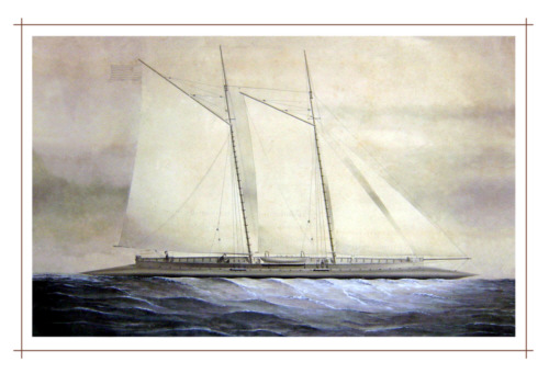
     In 2003, by applying all of these descriptions, I produced a speculative reconstruction illustrated later in this article.  But in 2009 I came across an extraordinary new source in the French Publication industrielle des machines, outils et appareils (Publication of industrial machinery, tools and apparatuses).  Volume 17, published in 1867, features an article, “Navigation à Vapeur - navire fusoiforme a hélice”114 (Steam Navigation - spindle-shaped screw steamer), that includes a detailed description of the "cigar-boat", apparently not yet named Walter S. Winans at the time of original publication and, in a separate volume of plates, a set of figures115 from M.M. Nillus and Son, the firm that constructed the boat.  This marvelous plate,  which I obtained from the Ecole Polytechnique Fédérale de Lausanne and, separately, from the Smithsonian Institution Libraries, provides us with engineering drawings of this cigar boat.  
Plate Image Courtesy of Smithsonian Institution Libraries
The above image is provided courtesy of the Smithsonian Institution Libraries.
 

     Per the Publication industrielle article114 and figures (shown above)115, the Walter S had seven interior compartments, three of which were large enough for regular access from the deck.  The engine room, amidships, was the largest, with the high-pressure boiler aft and the engines forward.  It's likely that this arrangement, combined with removal of some of the forward equipment, resulted in the bow-high appearance described in the Mercury.  The drawings support the Mercury assessment of inferior accommodations.  An ellipse-shaped gunwale topped with a rail surrounded the cluttered weather deck.  The deck had a small horizontal wheel at each end, a companionway with stairs into the forward cabin, and cylindrical hatchways with ladders into the engine room and aft cabin respectively.  The top of the boiler and stack rose above the deck between the hatchways just aft of amidships.
     The Walter S was designed as a test bed for various propeller configurations.  In addition to RossWinans-like, six-bladed propellers on each end of the hull, there were three auxiliary propeller shafts under the hull at each end, one below the centerline and two outboard.  The article indicates that “after inconclusive experiments” (“après quelques expériences peu concluantes”) the large propellers, shafts, and associated machinery were removed to allow the two cabins to be used for passengers.  The aft lower central shaft was extended and a large ordinary propeller was added for the cross-Channel voyage.

     The trip began in Havre at 5:30 in the morning, 28 March.  The boat traveled without incident over a rough sea and arrived at New Haven, England that afternoon.  The next day it continued along the shores of Brighton.  At 3:50 on the 30th it departed for Gravesend, arriving at 9:30 on the 31st after stopping in Dover to take on a pilot.  The map also shows London, where the Ross Winans was under construction up the Thames from Gravesend, and Southampton, where both boats were eventually anchored.

     The Walter S. Winans was designed as an experimental boat to test various propeller configurations.  The images just below show some of many possible configurations.  The first two show the usually mentioned configuration with a propeller on each quarter and one with two centrally-mounted submerged propellers.  

The view just above on the left shows the semi-submerged propeller configuration.  This is the propeller configuration  of the Ross Winans.  Different size propellers and different blade counts might have been fitted for test.  The image on the right shows the three-bladed, submerged propeller Channel-crossing configuration.

It's misidentified in the title as the Ross Winans, but modelshipmaster.com is building a beautifulClick for photos at modelshipmaster.com plank-on-frame model of the original Walter S. Winans.  The model maker has incorporated some features of the rebuild vessel, described below, perhaps even as the Winans kept thinking of improvements.  You can see photos of the completed model here.  Note that in addition to the identification, the accompanying text is wrong.  The cigar boats were built of metal and didn't use plank-on-frame construction.  Nonetheless, it's a beautiful model that nicely matches the drawing shown above as well as the propeller enhancements below.


In 1877, the Walter S. Winans was significantly modified at the yards of Day, Summers & Company in Southampton, its length more than doubled and its displacement tripled117,119-121.  As illustrated in the graphic below, approximately 21 feet of the hull was removed from each end.  The remaining hull was cut in half and a 58-foot cylinder inserted.  Cones approximately 36 feet long were added at the ends to achieve a new total length of about 151 feet.  No dimensions are provided for the superstructure, called "roundhouse" in the 1877-78 sea experiment logs120 that record how far water came above its bottom at its front, middle, and back.  The log remarks also state several times "no masts in vessel" implying there was provision for them.

1877 modification of WSW

     The logs provide little information about the internal configuration.  Drawings in the steering experiment logs119 show a bulkhead just aft of the rudder post.  Three forward compartments are mentioned as filled with coal but not explicitly identified.  The remarks for experiment 141120 state that the points at each end were filled with water "back to pantry bulkhead", forward and "up to bulkhead in men's place" aft.  The same remarks mention placing a men's place in the vessel's center.  Other remarks identify the fire room and a "tunnel" although "funnel" may have been intended.
     The logs mention bevel gears several times, a necessity with the propeller shafts placed a the extreme distance from the center of the hull cross-section, and the props are described as turning inward or outward in different tests.  The gearing was clearly changed from the original configuration with which both side props turned the same way.
     The separation of the original engine and boiler positions would have necessitated a
58-foot extension of the power shaft and steam lines so it's likely one or the other was moved.  The drawing above shows two possible repositionings of the engines, one forward the boiler in the same relative position as originally and one aft of it.  The first would have preserved the original steam piping.  Other practical configurations are possible.

     Per the textual remarks in the logs, the propeller arrangement appears to have been modified to a more conventional aft-only underwater configuration although each shaft had an unconventional setup with one or more two-bladed propellers spaced several feet apart.  The steering experiment logs119 indicate the use of only one rudder although different sizes were tried.  With propellers mounted only aft, it's likely that the internal arrangement was changed to move the engines aft as illustrated in the modifications drawing above.  

Six-propeller Configuration

     The logs describe a waterline with the forward end point approximately at the waterline but the stern point submerged two feet below the waterline.  Because considerable ballast was added to the three forward compartments119 to achieve this trim, the unladen configuration must have been quite stern-heavy.

Speculative Reconstruction of 1877 WSW

     For my reconstruction, I assumed hull plates in the new sections of similar size to the original construction with similarly spaced bulkheads.  The 1878 Taunt photo82 shows a drastically depopulated Ross Winans deck with neither stacks nor masts.  It is possible that these changes were made in 1877 concurrently with the Walter S. rebuild, with some of the superstructure and machinery recycled.  The Ross Winans engines were over 13 feet tall and tailored for the centerline propeller shaft, abandoned in the modified Walter S., so these were probably not transferred.  One of the four boilers would fit within the narrower hull, but removing it from the Ross Winans hull would have been difficult.  There is mention of a donkey engine feeding the boiler in the logs121, and this may have been taken from the larger yacht, which had one to operate the pumps44.  As stated above, the test logs mention masts.   The Winans may have intended to equip the new Walter S. with the Ross Winans masts, although they were not fitted for at least some of the tests.  (Then again see the sailing vessel painting below.)  Other deck parts missing in the Taunt photo, including the helm, may have been used as well.  The figure below, showing how the 1877 Walter S. deck might have looked fitted with parts from the ten-foot wide Ross Winans superstructure, illustrates the difficulty of installing parts from the larger yacht in a deck structure only six feet wide.  It is of course possible that Ross Winans deck structures were significantly modified for the smaller boat.
WSW with Ross Winans masts, companionways, & stack
     The illustrations above show a configuration with three propellers mounted on each shaft.  Numerous configurations with two, four, six, and eight propellers were tested using combinations of two-bladed propellers from 3 feet 7 inches to six feet in diameter and spaced at different distances along the shaft121.  For some tests the props were run with their tops rotating inward and some rotating outward.  The test logs also record coating the bottom with "Mr. Innes's composition", possibly to reduce friction.

James McNeill Whistler mentions anticipating a trip on the "smaller" cigar boat in a letter67 written in 1868.  An 1876 letter71 from Whistler's mother indicates Walter Winans planned in June of that year to sail it to the Isle of Wight.  There is evidence that other well-known figures also enjoyed excursions on the boat.

     The 1881 British census64 records that the Walter S. Winans was in Southampton, England on 3 Apr, 1881.  The only crew member listed is 54-year-old Richard Jordan, the "boatswane".  The Walter S does not appear in the 1891 census.  


An unknown artist created a pen and ink and watercolor painting73 of a two-masted sailboat with a cigar-shaped hull.  My first reaction was that this was a general application of the cigar hull to a sailing vessel, but John Lamb suggested it might be the Walter S since the two masts and bowsprit fit the description.   (Dodds5 is the only one I know of to mention masts and bowsprit for the Walter S.  I wonder if he had seen this painting or a similar depiction.)  Examination of the painting reveals no sign of steam power and the boat depicted appears to be about 125 feet long, much more than the reported original Walter S length.  The deck also occupies a much greater proportion of the total length.  Still, since the watercolor shares its provenience with what may be a very early impression of the Ross Winans, this could be an impression of a boat that eventually became the Walter S Winans.  The painting might also depict the Walter S after its 1877 renovations.
     The original art, which is heavily damaged, was purchased many years ago from a dealer who acquired it in a house clearance in somewhere in Portsmouth or Southampton, UK.

(Original courtesy of Gary Creighton)

     This artwork inspired me to create the below whimsical concept for the Walter S using masts like these rather than the steamer masts I chose for my original speculative concept.  

Restoration (Original courtesy of Gary Creighton)

Alternate speculative reconstruction of the Walter S. Winans

     I'd recognized the sloop rigging in the painting, but Steve Walk pointed out the resemblance to a particular sloop, the yacht America.   John Cox Stevens, who commissioned the America and won the first America's Cup competition was a friend of Ross Winans.
 

(Source citations are in the bibliography on the main cigar ships page.)


The following section retains my earlier speculation, now with comments about its accuracy.

My early speculative reconstruction of the Walter S. Winans
     In 2003 I produced the earlier speculative reconstruction concept illustrated in these graphics.  I combined the single and double propeller arrangement from Patent 58,743, but only at the aft end, taking the Engineer account literally.  In fact both ends were identical with a full set of four propeller shafts.  The scale I chose for these assemblies was larger than on the actual boat. I included the semi-submerged prop in the aft array.  This propeller was in fact integrated with the hull shape and at both ends, as on the Ross Winans, but I took a simpler approach, mounting a conventional prop on one end of the hull.  The plan above shows two quarter-mounted propellers at the bow and a single submerged prop at the stern.  All six propeller shafts and mountings are fitted.
     Except for Dodds' masts and bowsprit, the earlier descriptions did not mention a superstructure, but I chose from the decks described in Patent 161, 372.  Although not granted until 1875, this patent was originally written on
Four-propeller configuration - early speculative image
20 Jan 1866, according to the signature page, at the same time as a number of the patents granted in 1866.  For the small diameter of the Walter S, I chose a deck arrangement that cuts into the spindle hull.  My choices were close.  In fact the superstructure sat atop the hull, similarly to the Ross Winans, and was longer than I depicted.  I narrowed the ends to points, but the Nillus plans show them rounded.
     I included two telescoping masts, similar to the Ross Winans, reasoning that these would provide prudent propulsion backup if the engine failed on the dangerous Channel crossing.  The Nillus plans show no masts and the available space with the internal and external equipment configuration argues against them.  I placed a single stack approximately amidships, but omitted the problematic bowsprit.  The Ross Winans had an eagle figurehead on forward end of the deck structure.  I thought the Walter S might have had a similar ornament on a bowsprit.  The Nillus plans show nothing like these.  The Publication industrielle article describes the Walter S as an experimental boat, implying that there were no decorative elements.  The forward cabin does have a companionway  and staircase indicating there was some  accommodation for passenger convenience.  Lastly I showed a single conventional ship's wheel but the Walter S had a horizontal wheel at each end of the deck.
       

Comments and questions are welcome. E-mail me. Click to close and return

This page and its content © Copyright 2003, 2006, 2008, 2009, 2011 Michael & Karen Crisafulli. All rights reserved.
29 Sep 11